Field-ready guide for Ex d / Ex e applications under ATEX/IECEx. Covers SWA (steel wire armour) and X/Y/Z armour types (X = braid, Y = flat steel wire, Z = steel tape).
0) Audience & Safety
- For competent personnel working on certified Ex equipment.
- Always follow your company’s permit-to-work, gas testing, LOTO, and ESD procedures.
- This guide supplements the current Hawke instructions and data sheet for your exact variant/size; manufacturer documentation takes precedence.
1) Product & Parts (501/453 UNIV / RAC / RAC-L)
Typical components (nomenclature may vary by variant):

- Entry / Body (threads into equipment; earthing path)
- Armour Spigot (with inner/diaphragm seal)
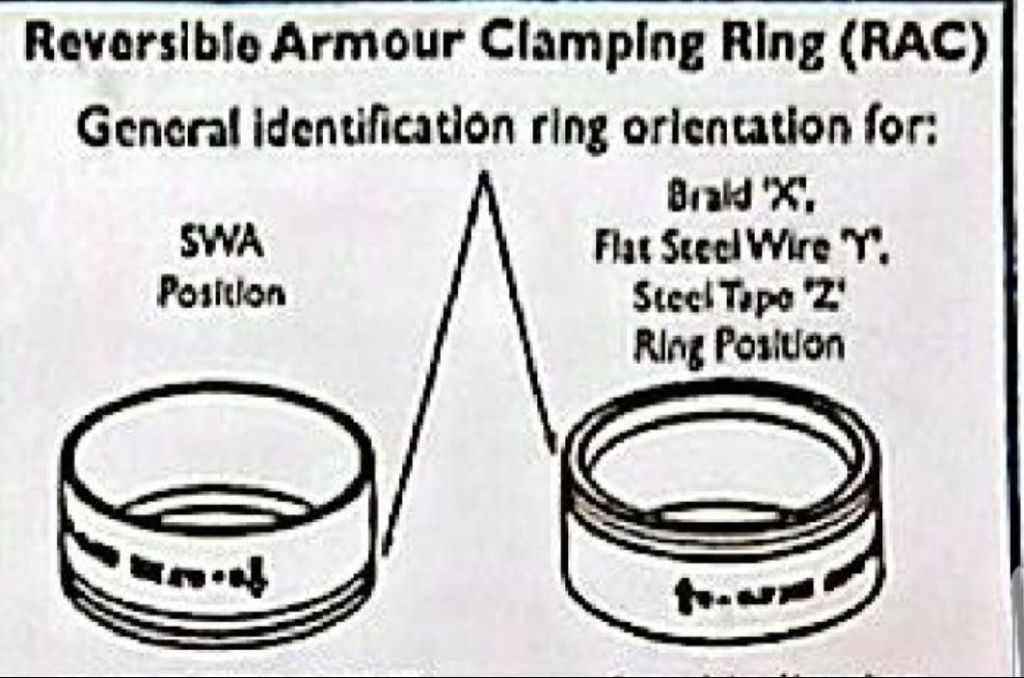
- RAC = Reversible Armour Clamping ring (two faces)
- Middle Nut
- Backnut (sets outer seal; includes Inbuilt Tightening Guide marks)
- Seals & Shrouds as supplied
- Sealing Washer/O-ring (for IP in Ex e / outdoor as required)
2) Choosing the RAC Orientation (Covers SWA and X/Y/Z)
Step A — By Armour Type
- Use RAC “SWA” face when armour is round steel wires (SWA).
- Use RAC “X/Y/Z” face when armour is braid (X), flat steel wire (Y), or steel tape (Z).
Step B — By Armour Thickness
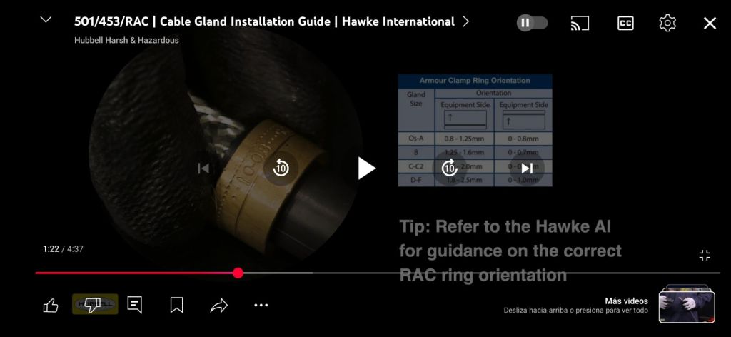
- Hawke specifies Orientation 1/2 depending on armour thickness.
- Select Orientation 1 or 2 strictly from the current Hawke size chart for your gland size.
- If the measured armour is outside the permitted range for that size, select the next gland size up.
3) Cable Preparation
- Slide onto the cable in order: backnut → outer seal / shroud (if used) → middle nut → RAC (keep its chosen face ready).
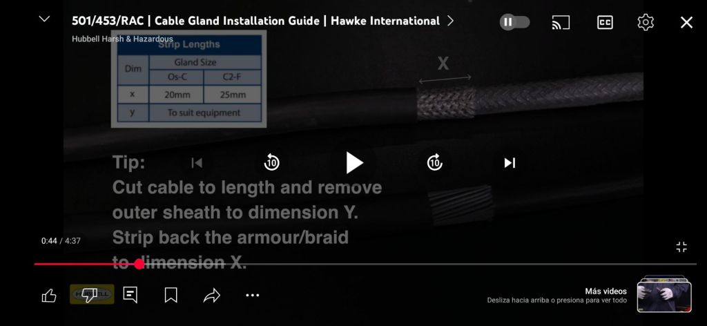
- Strip the outer sheath to the manual’s dimension “I” for your gland size (typical: ~20 mm for Os–C; ~25 mm for C2–F — confirm against the latest sheet).
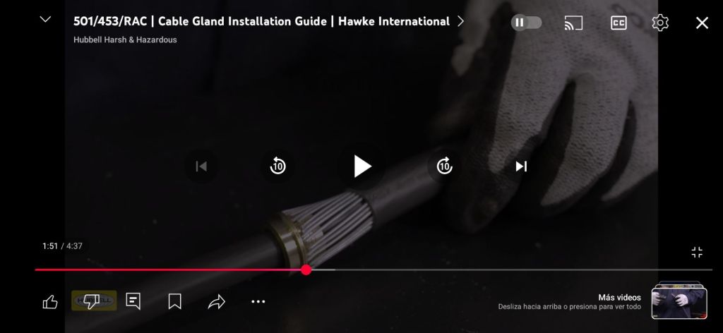
3. After clamping the armour/braid on the spigot, strip the inner sheath (bedding) to suit your termination; the manufacturer recommends leaving ~5 mm of inner sheath exposed beyond the gland entry before the conductor insulation begins.
4) Assembly (Applies to SWA and X/Y/Z)
- Mount the body into the equipment entry. Use a certified sealing washer/O-ring where IP66/67/69 or Ex e ingress protection is required. Tighten per equipment thread spec.
- Push the prepared cable fully home into the spigot/entry until bedding seats.
- Slide the RAC down with the selected face toward the armour and engage it so the armour is trapped onto the spigot shoulder 360°.
- Run up the middle nut hand-tight, ensuring armour remains evenly captured.
- Tighten middle nut then backnut to the Inbuilt Tightening Guide marks or the manufacturer torque value for the size. Do not over- or under-tighten.
- Fit shroud (if used). Confirm no twisting or gaps at seals.
5) Common Pitfalls to Avoid
- Using SWA face on braid/tape (or X/Y/Z face on SWA).
- Missing sealing washer where IP is required (typical Ex e mistake).
References (verified)
- Hawke 501/453/UNIV – Installation Manual (AI2000) — Step 3 shows 5 mm exposed inner sheath recommendation.
https://hubbellcdn.com/installationmanuals/AI2000_501_453_UNIV.pdf - Hawke 501/453/UNIV – Product Page
https://www.hubbell.com/hawke/en/products/501453univ-ex-d-ex-e-cable-gland/p/3913696 - Hawke 501/453/RAC – Assembly Instructions (AI302) — strip length “I” = 20 mm (Os–C), 25 mm (C2–F).
https://www.superlecdirect.com/media/pdfs/501-453-rac-installation-instructions.pdf - Hawke (official) – Installation video page (501/453/UNIV)
https://www.hubbell.com/hawke/en/videos/hawke-international-installation-of-501-453-universal-cable-gland/v/6318192222112 - YouTube (verified): Hawke Cable Gland Installation Guide — 501/453/UNIV
https://youtu.be/WHMipKK0stI
